Maximilian LIM JAKE YAng
Architecture Degree Works
Building Information Modelling - Work in Progress
Project 2B


Creating custom title block by choosing a A1 drawing sheet template

Editing texts into each box in title block

Adding a new phase and renamed to "Demolish"

Changing walls into existing construction

Existing construction walls are visible by changing the phase in properties panel
Adding a new phase and renamed to "Demolish"

Topography surface is created through the topography surface option in the massing & site tab.


Contour lines are adjusted through "site settings" located by clicking on the arrow on the model site panel. Unit at "intervals of" are adjusted under the "contour line display"
Topography surface is created through the topography surface option in the massing & site tab.

Doors and windows are tagged by using the "tag all" option under "annotate"

Doors and windows are tagged by using the "tag all" option under "annotate"

Room schedule option is applied


Fields are added through the schedule properties window.
Room schedule option is applied

Rooms are created by using the "Room" option under the architecture tab. Rooms are tagged with area in enclosed rooms

Rooms are then renamed

Window labels are renamed to alphabets for easier and more organized labelling
Rooms are created by using the "Room" option under the architecture tab. Rooms are tagged with area in enclosed rooms

Room legend is added through the "color fill legend" option in the annotate tab. Space type is chosen as "Rooms"

Colors are added automatically onto the rooms

Room legend is added through the "color fill legend" option in the annotate tab. Space type is chosen as "Rooms"

Section cut is created from the "views" tab
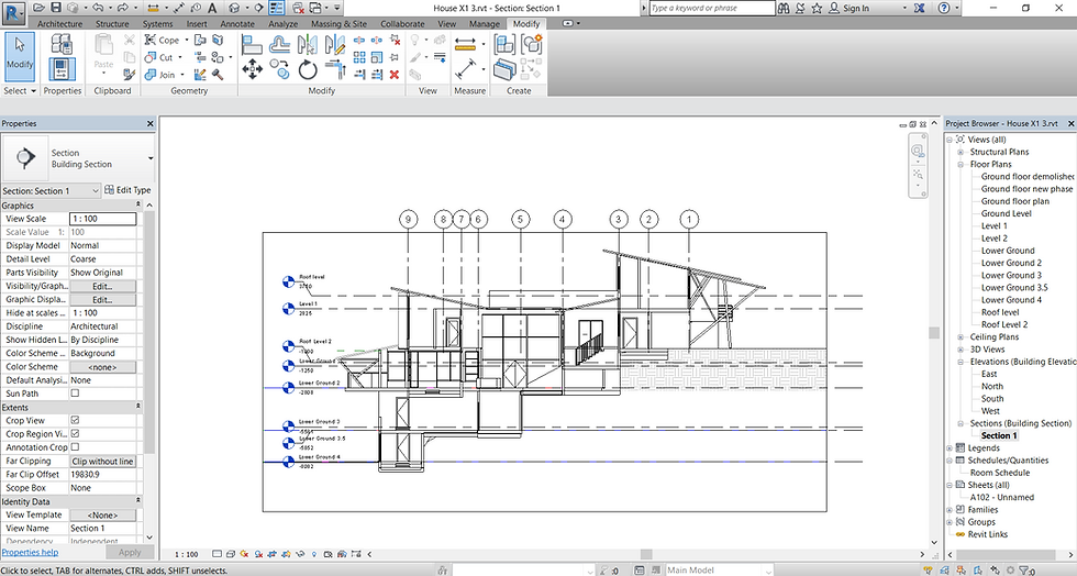
Section cut is created

Detailed section is created
Section cut is created from the "views" tab


Exploded isometric is created by selecting each floor and roof and group them together using the "displacing element" option. A gumball appeared to control the height of each group.

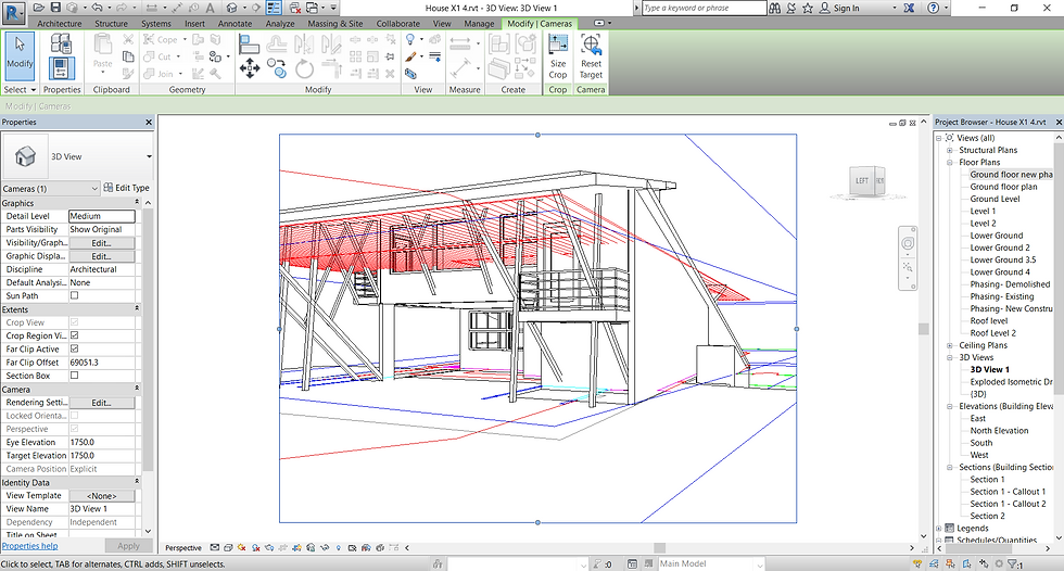
Exterior and interior perspective views are created by using the camera option. Camera is adjusted in the ground floor.

Site components are also added onto the site as trees.

Exterior and interior perspective views are created by using the camera option. Camera is adjusted in the ground floor.

Drawings are added into the drawings sheets by dragging the drawings to the sheet at the project browser panel. Additional sheets are added by right clicked "sheets" at project browser and by clicking "new sheets" Each sheets are then renamed and labelled according to correct and formal architectural drawing format

Drawings sheets are converted to PDF by using the "print" function.
Drawings are added into the drawings sheets by dragging the drawings to the sheet at the project browser panel. Additional sheets are added by right clicked "sheets" at project browser and by clicking "new sheets" Each sheets are then renamed and labelled according to correct and formal architectural drawing format